
AXS SMARTOBM QUICK REFERENCE USER GUIDE
01. Getting Started
1. Install or open your Truck OBM App. If you haven’t already create an account to get started.

2. Find your AXS serial number to create the account, this is located underneath the scales.
Warning: Hazardous or unsafe practices may result in severe injury or death. Only an authorised dealer or specialist should install, repair, remove, or reinstall the unit. Ensure the product is connected to the correct power and air supply. Refer to the rating label and general specifications for proper installation.
Important: Do not connect the unit directly to the vehicle battery or a permanent power source.
02. Specifications
Electrical
|
Input Voltage | 7 - 32VDC
|
|
Power Consumption | Typical Average 100 mA @12V DC
|
|
Protection | Reverse and Over Voltage Protect
|
Mechanical
|
Display | 5 Digit 7-Segment LED
|
|
Dimensions | 80x80x55.8mm (HxWxD)
|
|
Materials | Base: 6061 Aluminium Cover: Polycarbonate Ring: LED
|
Communication
|
Wireless | Bluetooth 5.3
|
|
Wired | RS232
|
Environmental
|
Operating Temperature | -40 to + 85°C
|
|
Dust and Water Ingress | IP66
|
|
Materials | Base: 6061 Aluminium Cover: Polycarbonate Ring: LED
|
Sensors
|
Pressure | Ceramic Pressure Sensors (Accuracy ± 0.5 % Full Scale
|
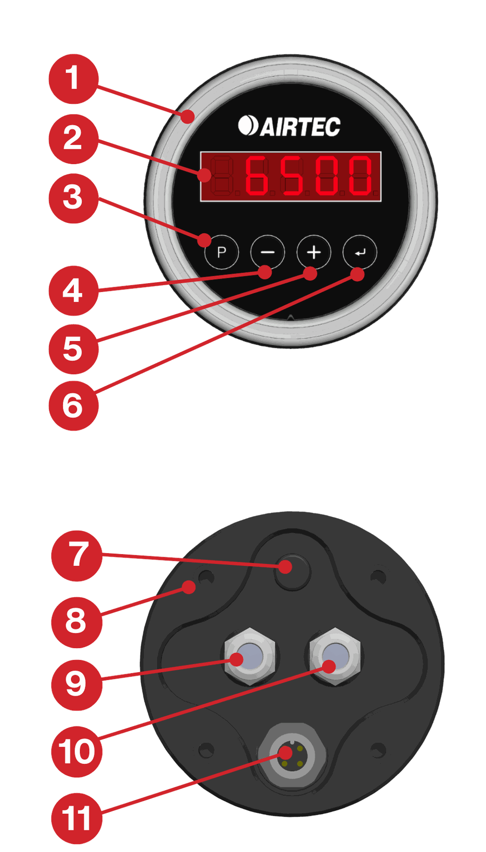
03. Product Overview
- LED Ring
- 7-Segment LED Display
- [P] Program Button
- [-] Subtract Button
- [+] Add Button
- [] Enter Button
- Pressure Compensation Vent IP (Protection)
- M5 Mounting Holes x4
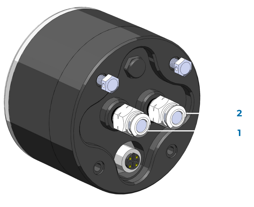
- Pressure Sensor 1
- Pressure Sensor 2
- Power (7-32VDS) and RS232 Connector
04. Installation
Location
Choose the optimal mounting position for the AXS on each axle group, ensuring a clear line of sight between scales.
Note: If drilling the chassis is necessary to mount the scales, confirm that this is permissible with the manufacturer.
Mount the scales facing outward. A mounting bracket may be needed for installation on the dolly or prime mover. Avoid mounting the scales inside enclosures or near heat sources/exhaust systems.
TCA Compliance 
For TCA Compliance, installation must be completed by an authorised Airtec Technician and an Installation Log must be completed and emailed to: [email protected]
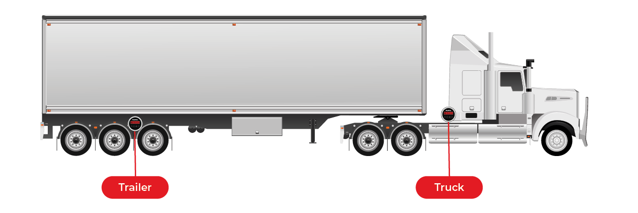
Mounting
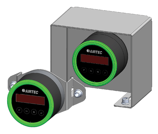
Mount the unit in a suitable position on the outside of the truck or trailer. The unit must be mounted so that it is level and out of direct sunlight.
Airtec has a range of mounting brackets available to suit your vehicle type.
Air Supply
Connect the air system to the airbag side of the ride height control valve. Attach the fitting and reduce the size to ¼”. Run a ¼” airline from the fitting to the scales, and insert it securely into the fitting.
Tips
For faster pressure stabilisation, run a larger air line closer to scales and reduce to ¼“ airline at the scales. Dual Sensor scaless can be plumbed to single height control airbag systems - either side for quicker response time but you can't use a single sensor on dual height control airbag systems.
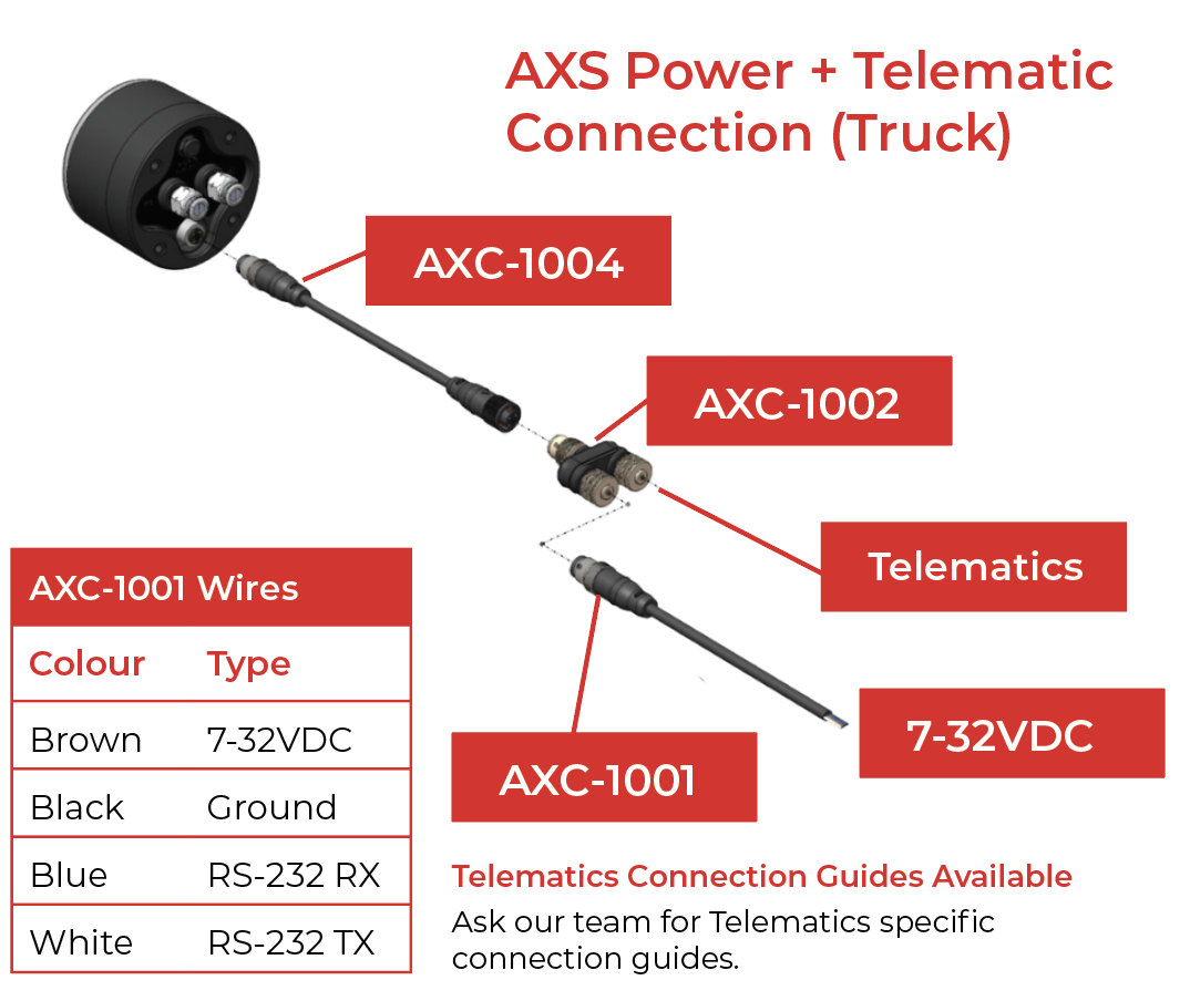
AXS Power Only Connection (Trailer)
AXC-1001- Cable

Important Installation Note:
All scales must be powered by a fused, 12-24 volt power source, activated by ignition status 'on'. Airtec does not recommend powering AXS Scales from the vehicle's EBS (Electronic Braking System). If you must power the AXS Scales through the EBS system, please consult the EBS manufacturer to ensure proper installation and compatibility.
05. Digital Lock
The digital lock is to prevent tampering of your scales’ calibration. If the lock is enabled:
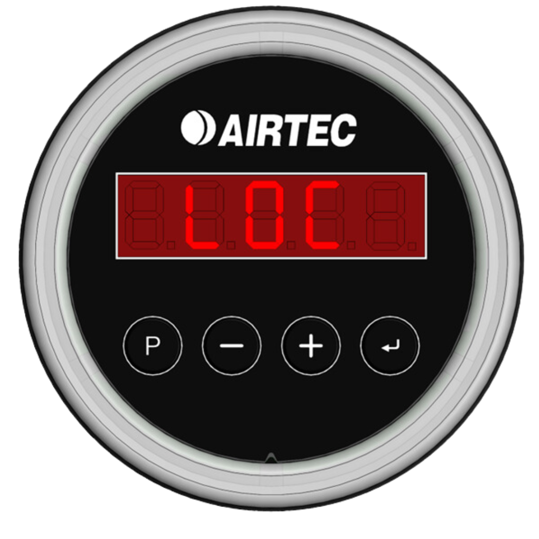
STEP 1|
Press and hold the [P] button until the word CAL appears on the screen. Press the [] "Enter" button and LOC will appear on the screen.
STEP 2|
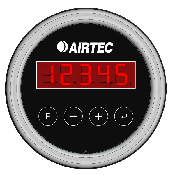
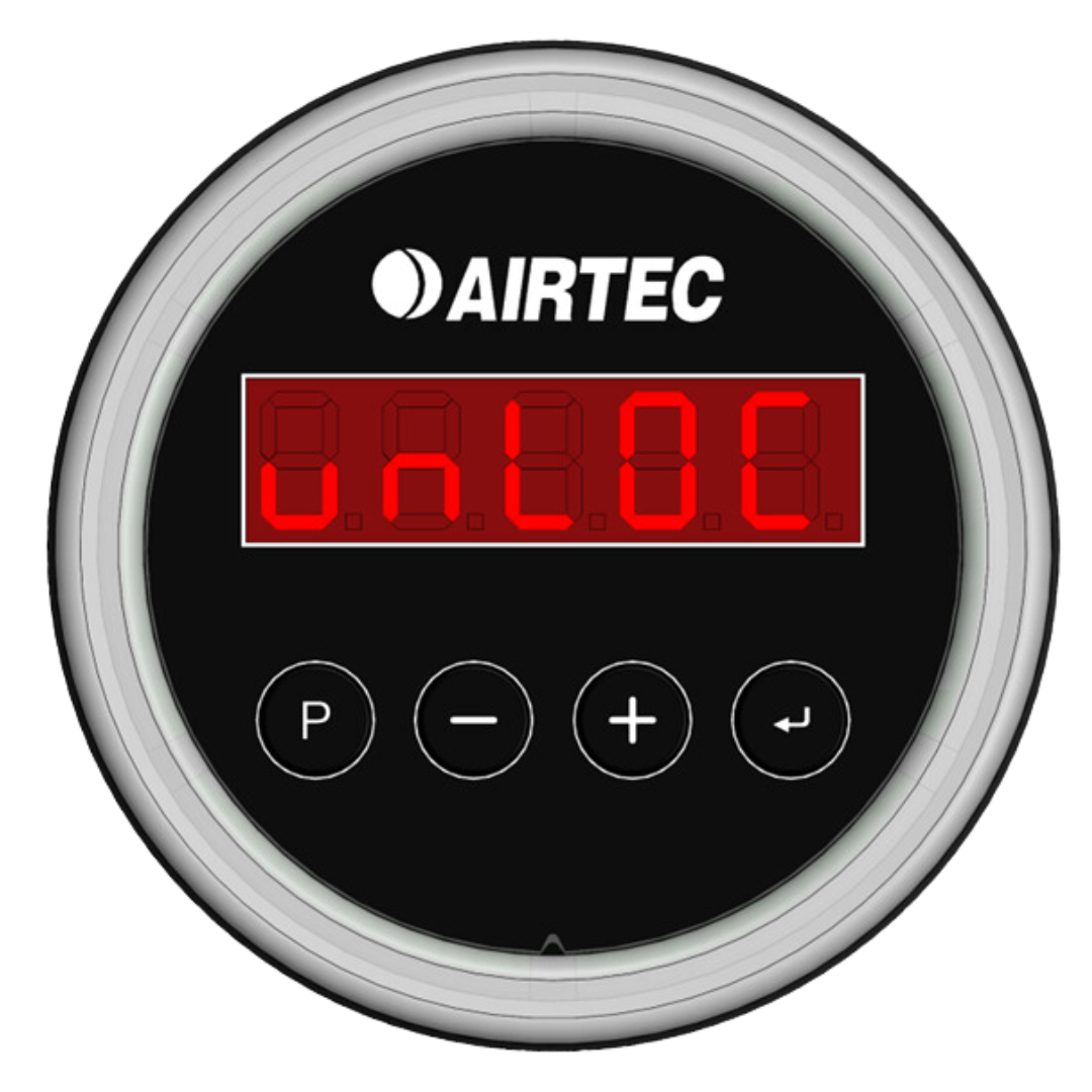
Press [P] then using the [-] and [+] buttons scroll through until you reach your 5 digit lock code then press [] "Enter". If correct, the word UNLOC will appear on the screen.
STEP 3|
Press the [] "Enter" button to enter the calibration mode.
06. Troubleshooting
Fluctuation/Erratic Reading
Electronic Height Control Valves can cause erratic readings - try lowering the suspension then re-inflate to drive ride height, to get a stable reading. Calibrate the scales using the same process.
Fluctuating with weight readings can be caused by worn height control valves not settling in the same positions. Check for leaks/worn linkages.
Dump Test Procedure
A dump test can be carried out to trouble shoot fluctuation issues.
Use an air bag dump valve and lower air bag pressure, scales readings should go down as the airbags deflate.
When the airbags are deflated, re-inflate the airbags back to ride height. The scales reading should come back to the original value.
Important
Calibration must be performed by an authorised Airtec Technician. A completed Calibration Log must be emailed to: [email protected].
Steps for Accurate Calibration
1] Engine Running
Ensure the engine is running to provide air to the suspension system.
2] Level Ground
Park the vehicle on level ground to ensure accurate readings.
3] Release Brakes
Release the vehicle’s brakes. If a trailer is attached, also release the trailer brakes.
4] Air Suspension Adjustment
Fully exhaust the air from the suspension system. Re-inflate the airbag suspension to the correct ride height.
5] Confirm Calibration
To complete the calibration, enter the weight displayed on the weighbridge into the scale or the app. Note: A margin of error of up to 0.2% between the values is acceptable.
Tare Weight (Empty Weight) Calibration
1] Weighing the Vehicle
Drive the full combination onto a split weighbridge to obtain each axle group’s tare weight (empty weight).
2] Enter Tare Weight
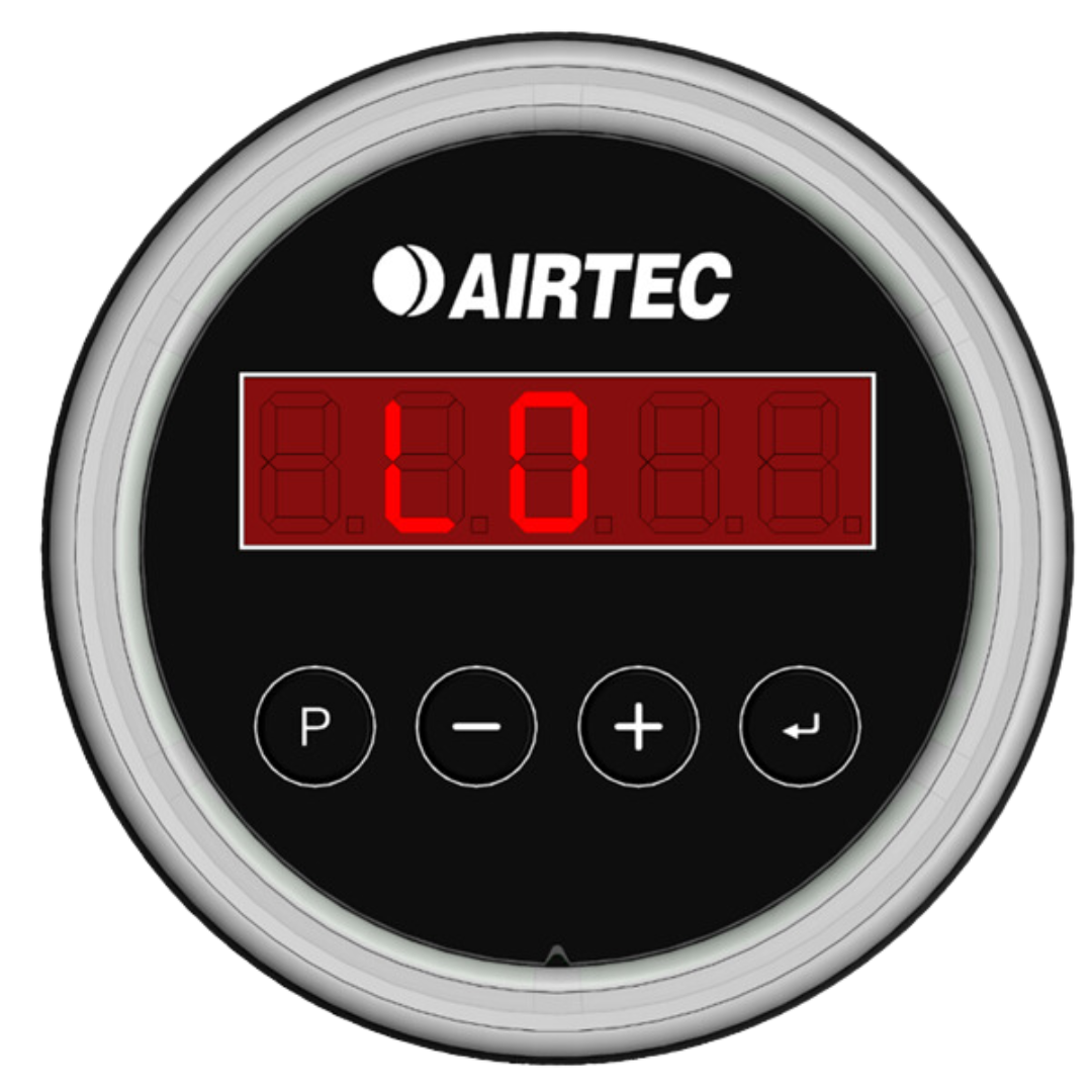
Enter the tare weight values for each axle group into the corresponding LO value fields on the AXS unit and store the values by pressing the [Enter] button.
3] Fuel Tanks
For more accurate readings, ensure fuel tanks are low during the tare calibration.
4] Alternative Entry Location
If you cannot enter values on the weighbridge, drive to a flat road area where the values can be safely input. Ensure wheels are chocked and the vehicle’s brakes are off.
Loaded Weight Calibration
1] Load the Combination
Fully load the combination to its maximum capacity and ensure the fuel tanks are full.
2] Weighing the Loaded Vehicle
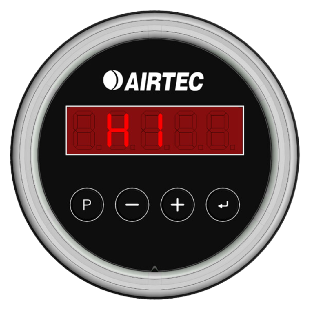
Repeat the process on the split weighbridge to obtain the loaded weight (HI Value) for each axle group.
3] Enter Loaded Weight
Enter the loaded weights into the corresponding HI value fields on the AXS unit and store the values by pressing the [Enter] button.
Final Steps
Complete the OBM Calibration Checklist: Ensure all required fields are filled out.
Submit to Airtec: Email the completed checklist to [email protected].
Responsibility
It is the fleet manager’s responsibility to ensure that the fleet remains compliant, and that calibration reports are obtained and kept up to date.
07. Single Channel Calibration
Setting the Tare Weight
Empty Vehicle Value
- With the AXS display on press [P] for 2 seconds to enter Program Mode (CAL will appear).
- Press [Enter] to enter calibration (LO will appear).
- When LO appears press [P] to adjust weight readings from factory settings.
- Adjust the value with [-] and [+] until the reading is the same as the weighbridge docket.
- Press [Enter] to save the tare weight.
- Press [P] until you exit Program Mode.
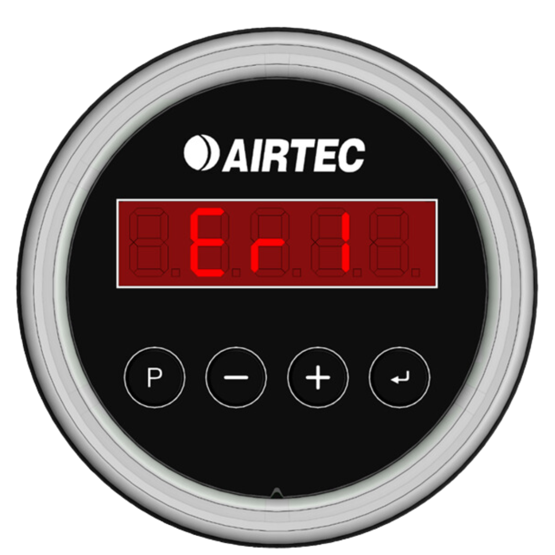
Error 1
Error 1 indicates calibration error, caused when both LO and HI have been set with the same airbag pressure. Please follow the steps outlined previously.
Setting the Load Weight
Full Vehicle Value
- Press [P] for 2 seconds to enter Program Mode (CAL will appear).
- Press [Enter] to enter calibration (LO will appear).
- Press [P] twice more to display HI, press once more to adjust the load weight.
- Adjust the value with [-] and [+] until the reading is the same as the weighbridge docket.
- Press [Enter] to set the load weight.
- Press [P] until you exit Program Mode.
08. Dual Channel Calibration
Select Axle for Calibration
- Press [P] for 2 seconds to enter Program Mode (CAL will appear).
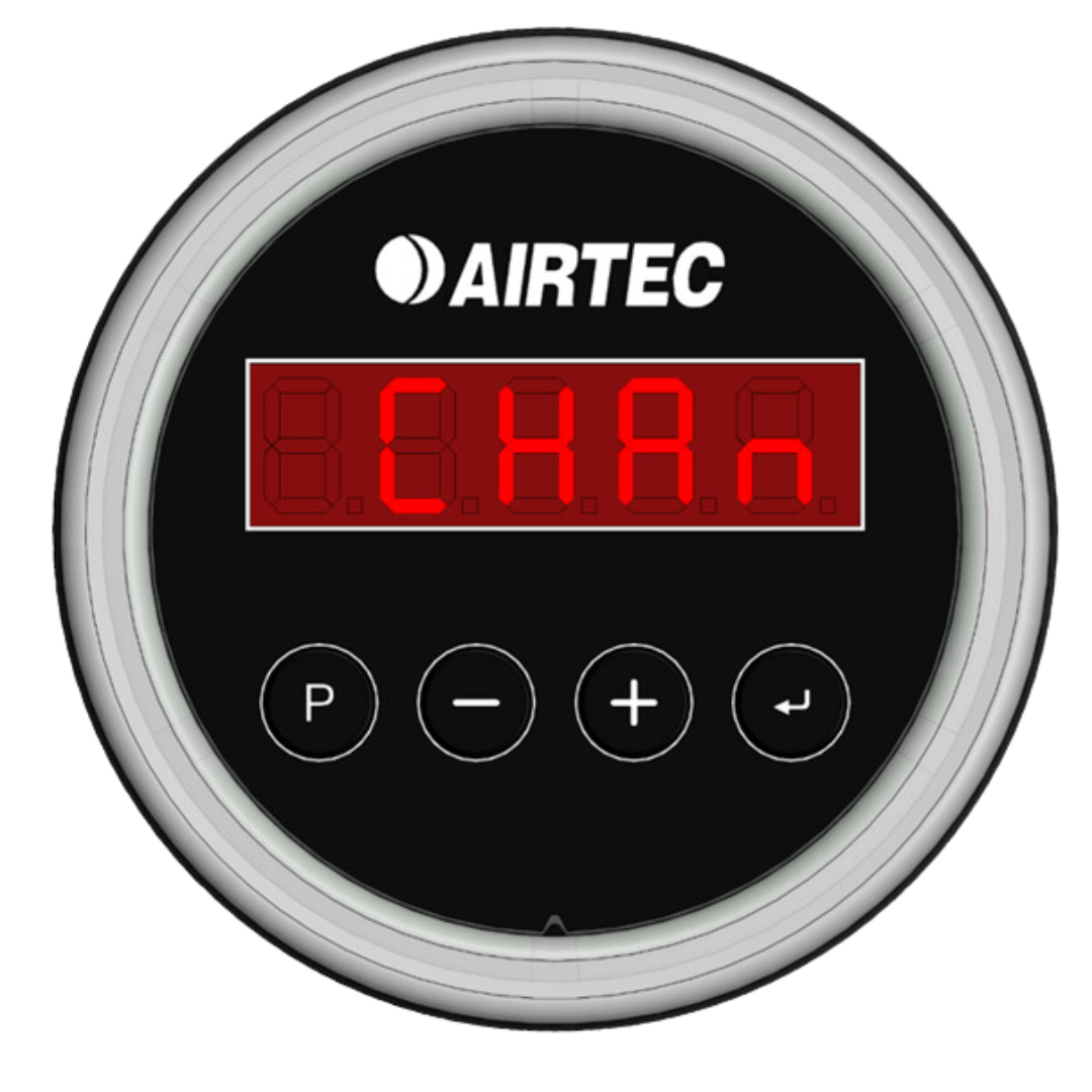
- Press [Enter] to enter calibration (CHAn will appear).
- Press [P] the display will show ‘--1--’ to indicate axle group 1.
- Adjust the axle group with [-] and [+] set the axle group by pressing [Enter]
Setting the Tare Weight
Empty Vehicle Value
- Press [P] for 2 seconds to enter Program Mode (CAL will appear).
- Press [Enter] to enter calibration (CHAn will appear).
- Press [P] the display will show ‘--1--’ to indicate axle group 1.
- Adjust the value with [-] and [+] set the axle group by pressing [Enter] (LO will appear).
- Press [P] once more to adjust the tare weight.
- Adjust the value with [-] and [+] until the reading is the same as the weighbridge docket.
- Press [Enter] to set the tare weight.
- Press [P] until you exit Program Mode
Setting the Load Weight
Full Vehicle Value
- Press [P] for 2 seconds to enter Program Mode (CAL. will appear)
- Press [Enter] then [P] twice more to display HI, press [P] once more to adjust the load weight.
- Adjust the value with [-] and [+] until the reading is the same as the weighbridge (or known weight).
- Press [Enter] to save the load weight.
- Press [P] to exit.
09. How to use Single and Dual Channel Scales
Read this section if your AXS is pre-configured from the factory with Dual-Channel option.
Follow these steps to set up your AXS axle load indicator to view the weight from each channel.

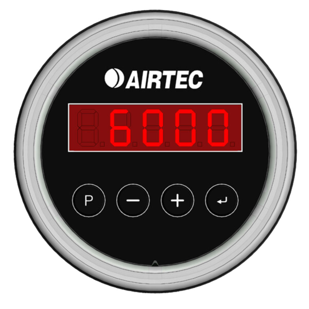
STEP 1
Press the [ENTER] button once to show the first weight. A number ‘--1--’ will flash in the display indicating “Axle 1” and following the weight value from the Axle Group 1 will flash in the display e.g ‘6000’.
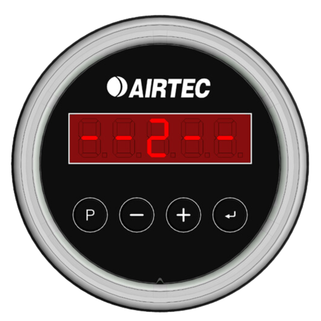

STEP 2
[+] button again until ‘--2--’ appears in the screen. The weight data corresponding to the Axle Group 2 will flash after a few seconds e.g ‘17000’.
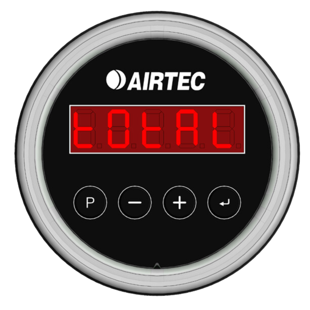
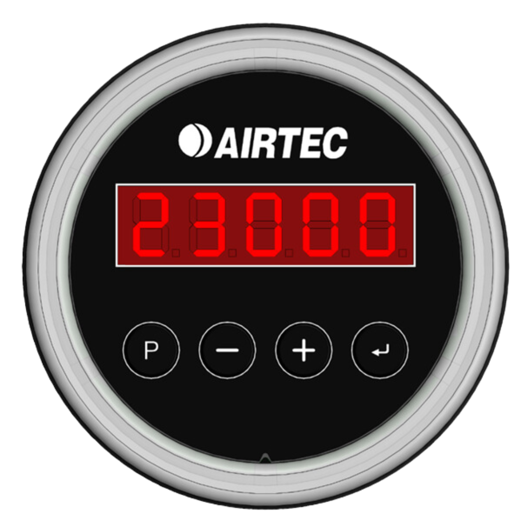
STEP 3
[+] button again until ‘Total’ appears in the screen. The weight data corresponding to the total will flash after a few seconds e.g. ‘23000’.
10. How to Program your Scales
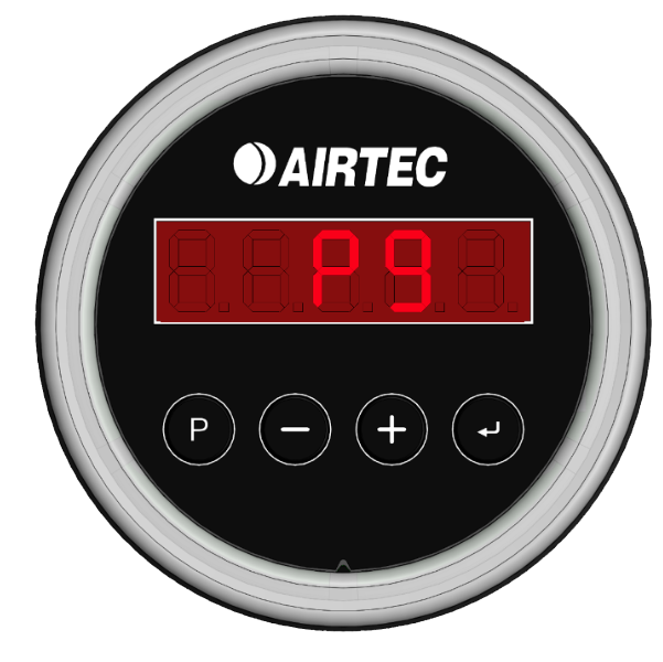
How to set Pressure Gauge Mode - Pg
The Pressure Gauge Mode switches the display from kilograms (kg) to kilo-Pascals (kPa), which is useful for diagnosing air suspension and calibration issues.
To enter Pressure Gauge Mode, hold the [P] button for two seconds until CAL appears. Press the [P] button until the display shows Pg. Press the [] button to confirm and switch to Pressure Gauge Mode. The display will now show pressure in kPa, with the decimal point indicating it is in pressure mode.
Hold down the [P] button for two seconds to exit Pressure Gauge Mode.
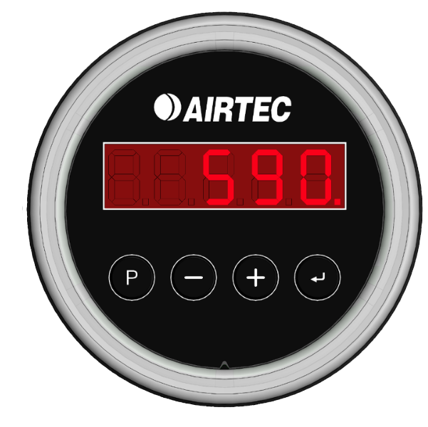
kPa Display Output
Enter Pressure Gauge Mode
How to set AXS Display and LED Ring Timeout
To set the timeout for the display and LED ring to turn off, press and hold the [P] button for 2 seconds, then press it once until DISP is displayed.
Press [P] once more to adjust the display timeout.
The display will show the timeout in minutes. Use the [+] and [-] buttons to adjust the setting.
[] to save.
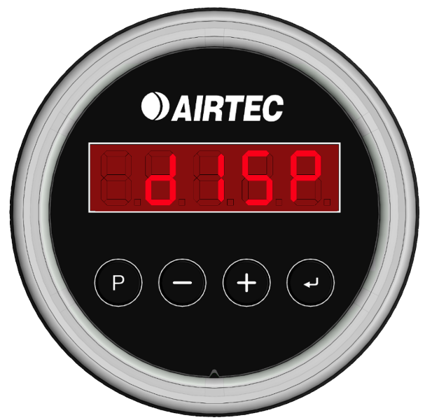
Set Display Timeout
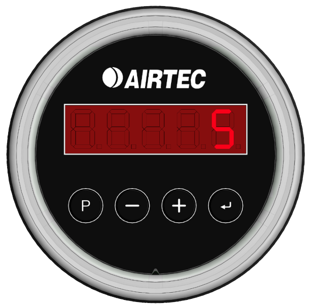
Display Timeout 5 minutes
Channel 1 Target Weight LED Colours
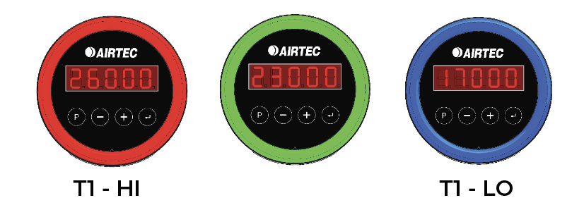
The LED ring changes colour based on the set target weights
Blue indicates the scales are below the target weight.
Green indicates the scales are at the target weight.
Red indicates the scales are above the target weight.
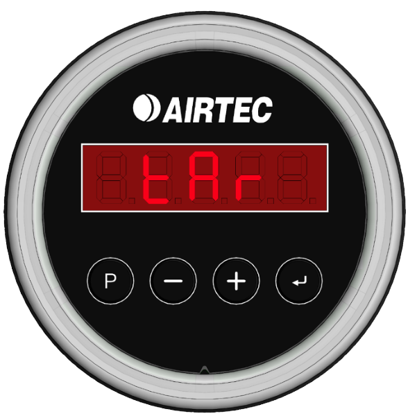
To set the target weights, hold the [P] button for 2 seconds, then press [P] again until the display shows TAR. Finally, press [] to confirm.
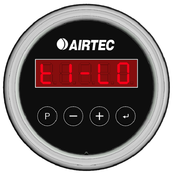
The display will then show the channel 1 low target. Press the [P] button once then press the [+] and [-] to set the channel 1 low target weight. Press the [ENTER] button to set it.
Set Channel 1 low target weight - Weight to 6000kg
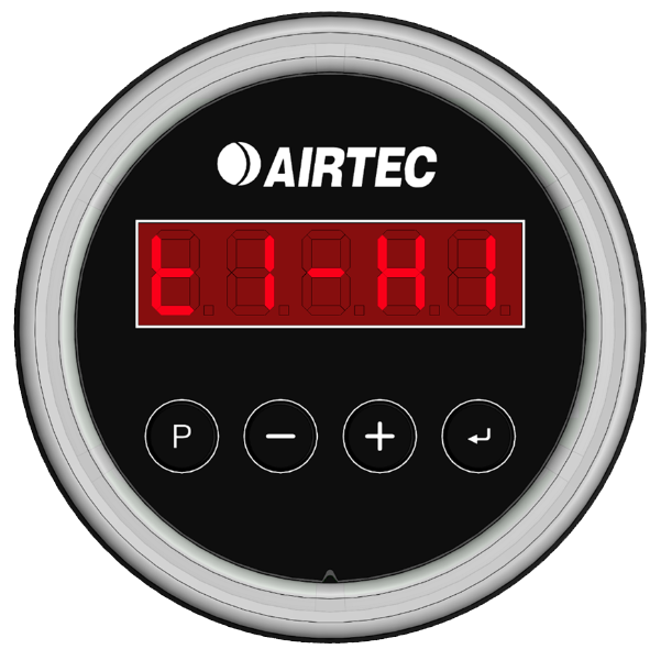
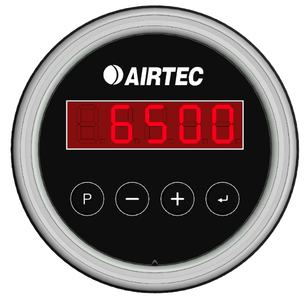
The display will then show channel 1 high target. Press the [P] button once then press [+] and [-] button to set the channel 1 high target. Press the [ENTER] button to set it.
Set Channel 1 high target weight - Weight to 6500kg
If the scales has 2 channels, repeat the process for channel 2.
Note: To disable any of the LEDs set any of the target weights to 0. These actions can also be completed within the App
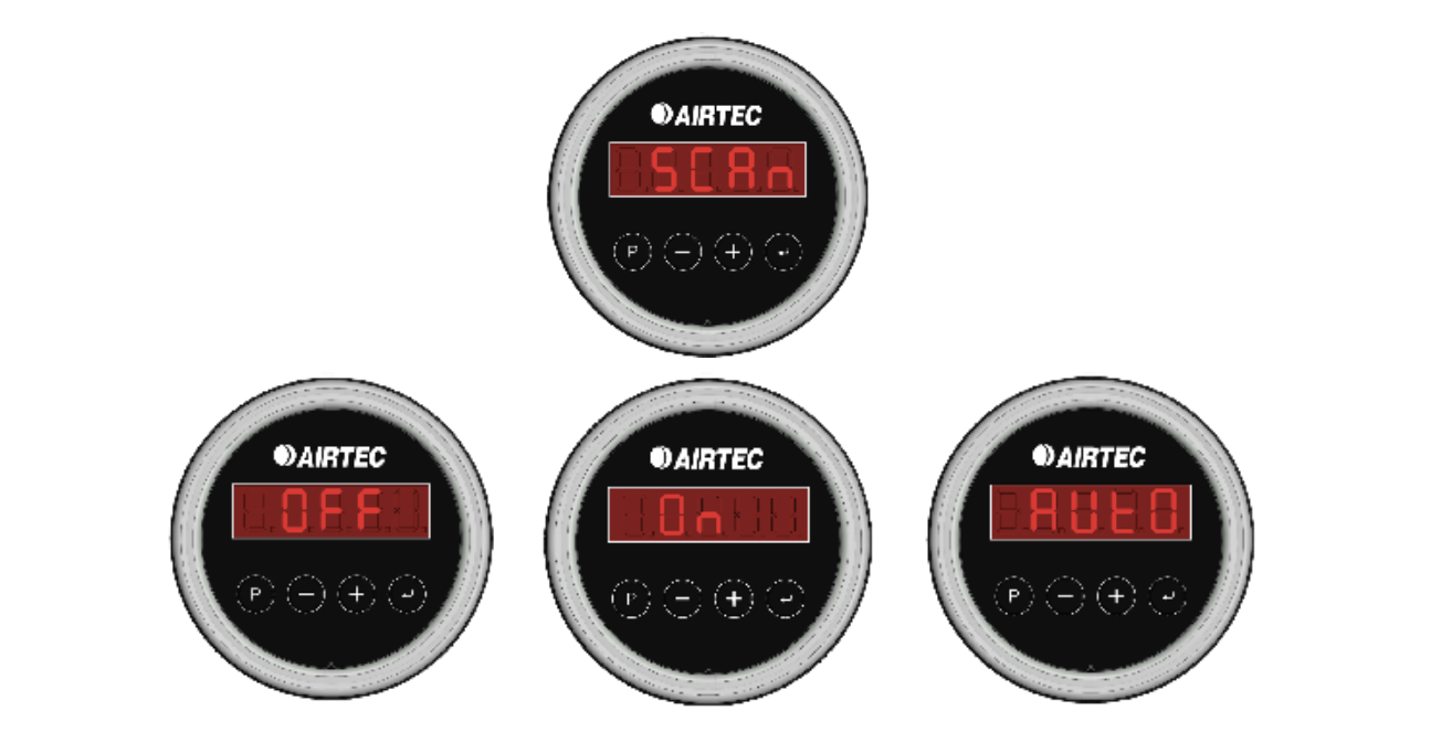
The AXS scan mode can be set to Off, Manual Scan, or Auto Scan.
Manual Scan Mode:
Requires the operator to manually scan the truck/trailer combination (see Section 13).
Auto Scan Mode:
Automatically scans the truck/trailer combination every time the combination is powered on.
To Set the Scan Mode:
- Hold down the [P] button for 2 seconds.
- Press the [P] button until the display shows SCAN.
- Use the [+] and [-] buttons to select the desired scan mode: Off, On, or Auto.
- Press the [] button to confirm and set the mode
Note: All AXS Gauges need to be set to Auto Scan for this feature to be successful across multiple devices.
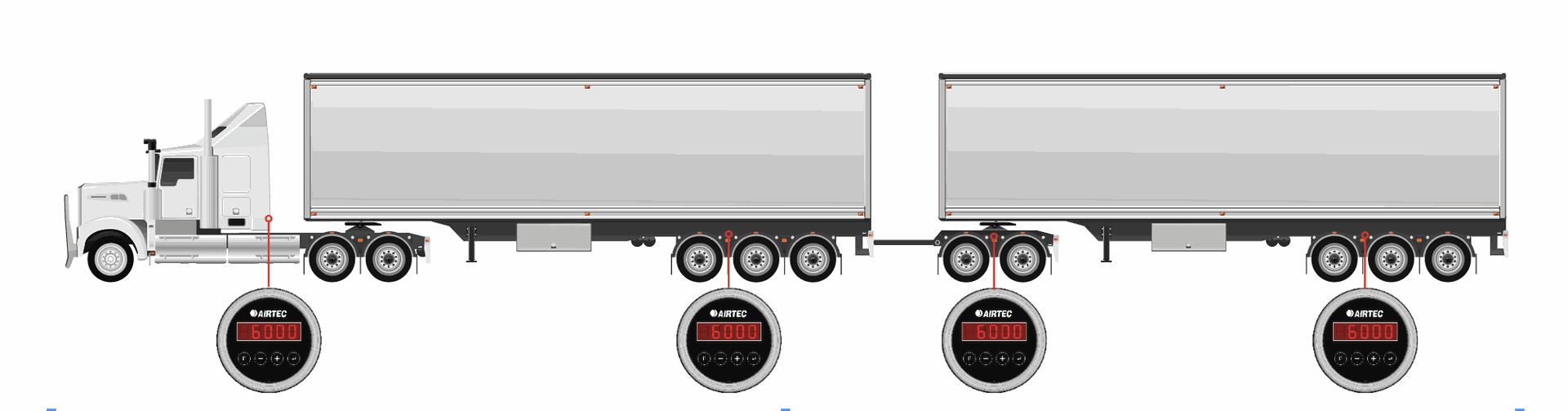
1. |
Ensure the Airtec AXS Scales are set to Manual Scan mode. |
2. |
Press and hold the [ENTER] button on the AXS Truck Scale until the unit is flashing the word SCAN. Note: All the trailer scales in range will flash and show SCAN. |
3. |
Press the [ENTER] button on each trailer unit in order of your trailers. First trailer 1, then trailer 2 (SCAN stops flashing on the screen). |
4. |
To finish the pairing process press the enter button on the AXS Truck Scale - it will stop showing SCAN. |
Note: The truck scale must be pressed last for scanning to be successful.
The AXS is a Transport Certification Australia (TCA).
Type-Approved Mass Sensor Unit part of the Type-Approved On-Board Mass (OBM) system. The TCA organisation approves automotive technology that follows a set of guidelines to ensure consumer safety and device reliability. For more information visit: tca.gov.au.
The AXS is approved for use in both Category A and Category B Type-Approved OBM systems. In order to comply with the TCA requirements, the below guidelines must be followed:
Guidelines for TCA Compliance
Category A & B
Installation, Calibration and Maintenance of category A & B systems must be completed by an authorised Airtec technician.
Category B only
The prime mover must have an approved telematics device installed and the device must be connected to the Airtec SmartOBM system.
To find out more about our authorised technicians or if you have any questions about category A & B compliance, please contact us.
P: 1300 818 884 | E: [email protected]
COPYRIGHT
This operations manual is protected under copyright laws. No part of this manual may be reproduced, distributed, translated, or transmitted in any form or by any means, electronic or mechanical, including photocopying, recording, or storing in any information storage or retrieval system, without the prior written permission of Airtec Corporation.
Airtec Corporation reserves the right to change specifications, modify designs and discontinue items without incurring obligation and whilst every effort is made to ensure descriptions, specifications and other information in this manual is correct, no warranty is given in respect thereof and the company shall not be liable for any error.
Copyright © 2024 Airtec Corporation Pty Ltd. All rights reserved.